2026-08-04 mitch
The Part
The WorldSemi WS2812b is a popular family of inexpensive, chainable, addressable RGB LEDs with a built-in driver chip that uses a simple, one-wire communication protocol. The part is used in many boards, notably by Adafruit, which calls them "NeoPixels". They're so prevalent that the core Micropython kit implements a module for them. Given all this attention, I won't pretend that I have anything new or interesting to say about this part in general.
The Mystery
The mystery I encountered with the WS2812 came from a horribly-soldered ground pin on the μC I was using to talk to it. Somehow, the pin kept it grounded for the first few minutes of work, then the connection broke (perhaps due to current-induced heating) and the LEDs didn't go completely dark, they just got much dimmer. Later, when I discovered the fault, I tried disconnecting the ground wire from the LED board completely and got the same behavior. A quick search lead me to some useless forum discussion, where someone asking exactly why this part worked without a ground wire was abused by a small mob of world-beaters. The only interesting thought was the OP returning later to post that this was likely the result of "parasitic grounding", which probably isn't a real term, but I think I caught his drift. At any rate, the part must be grounding through the data-in (DI) line, as there is no other possibility.
It's not hard to picture some current flowing between VDD and DIN when the latter is pulled low, but I don't understand how anything works when both VDD and DIN are at 3.3v (DIN high). To add to the confusion, I also tried a groundless wiring where VDD was 5v and DIN high was 3.3v, and this behaved a whole new way. So I hooked everything up to a scope to see if it would offer any more insight.
The Rightish Way (3.3v VDD, DIN, VSS (ground))
The true right way to wire this part is 5v VDD and DIN, but it usually works perfectly well (albeit less brightly) with 3.3v wiring, and my μC runs at 3.3v, so I used that. More importantly, this configuration used a ground line (called VSS on the datasheet). The LEDs worked as expected, driven by a program that set them each to a different color and rotated them every second. An arbitrary glimpse at DIN looked like this:
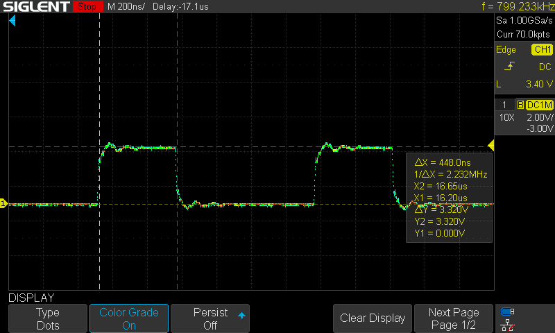
Here, DIN is moving between 0v and 3.3v, as expected. Unrelated to this experiment, but interesting, is the timing of what the datasheet calls T0H: the time that a 0 bit is held high. The datasheet states a valid range of 220ns-380ns, but all of these measured nearly 450ns. Despite this, the ring of 12 WS2812bs behaved as expected, so there's evidently a lot of wiggle room in that spec (or my scope needs calibration).
Dim and Groundless (3.3v VDD, DIN, no VSS connected)
This was the configuration I stumbled on initially, and that lead to this investigation. Without the ground wire, the LEDs continued to rotate, per the program. However, they were much dimmer, appeared to only be red, and the ones whose programmed color had no red component didn't seem to be lit at all. Here's what DIN looked like:
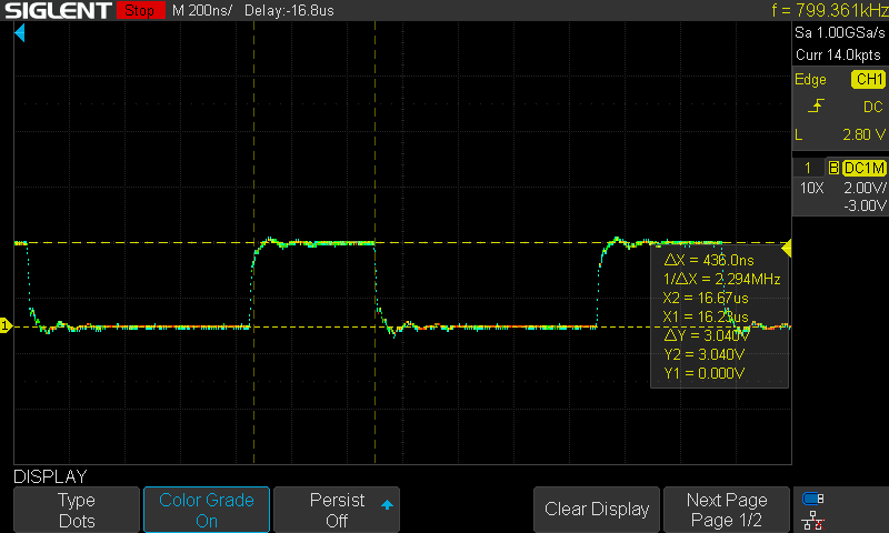
I still don't get the theory, but DIN was still being modulated correctly by the controller, and the chip in the WS2812b was operating and receiving correctly, for all I know. The voltage at DIN high was reduced a bit (down 0.3v to 3v), and while I doubt this explains the significant dimming, it may explain why the green and blue LEDs stopped functioning. On page 4 of the datasheet (actually the third page in the PDF), under "LED Characteristics", the table shows that the green and blue LEDs have a much higher operating voltage than the red one, and those voltages are very close to 3v. It's possible that the slight reduction in voltage dropped below spec for those two LEDs, leaving only the red one operational.
Bright and Static (5v VDD, 3.3v DIN, no VSS connected)
The last configuration was to move VDD to the 5v power rail (from 3.3v). This made the LEDs even brighter than the grounded 3.3v config and restored the function of the green and blue ones. However, the array of LEDs took on seemingly random colors, and did not rotate afterwards, despite the controller attempting to program them every second. A sample of the DIN just after power on looks like this:
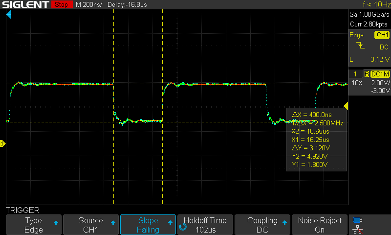
The interesting thing here is that DIN only went down to 1.8v (not 0v) when pulled low, although it now went high at 4.9v, so the difference was the usual 3ish volts. The consistent delta might explain why this initial signal had some effect on the driver, even though the colors seemed random. However, a second or so after power up, DIN looked like this:
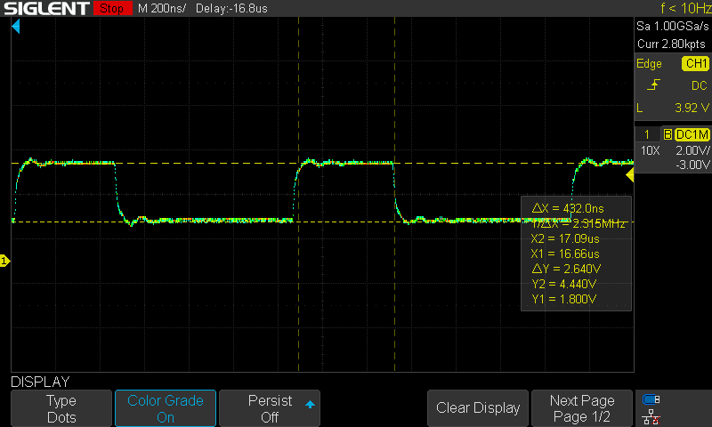
DIN high had dropped to 4.4v and, perhaps as a consequence, the driver stopped responding to the signal. At least, none of the LEDs seemed to change, despite DIN's modulations.
Conclusion
There's no real satisfying conclusion here, besides the lessons learned early on: double-check your solder jobs, and it's important to stay grounded.